PROGRAMMING LANGUAGES
The microcontroller executes the program loaded in its Flash memory. It is a so called executable code which consists of a seemingly bizarre sequence of zeros and ones. Depending on the microcontroller’s architecture, this binary code is organized in 12-, 14- or 16-bit wide words. Every word is considered by the CPU as an instruction to be executed during the operation of the microcontroller. As it is much easier for us to deal with hexadecimal numeric system, the executable code is usually represented as a sequence of hexadecimal numbers called a Hex code which, long time ago, used to be written by the programmer. All instructions that the microcontroller can recognize and execute are collectively known as the Instruction set. For PIC microcontrollers with 14-bit wide program words, the instruction set includes 35 different instructions.
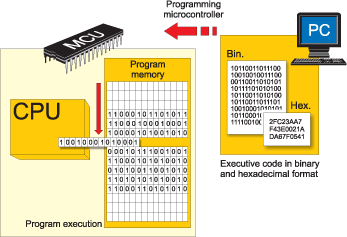
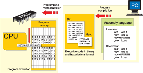
As the writing of executable code was endlessly tiring, the first high-level programming language called assembly language was created. It made the process of programming a bit more complicated, but on the other hand the process of writing program stopped being a nightmare. Assembly instructions consist of meaningful abbreviations which are compiled into executable code by means of a special program installed on a PC called assembler. It compiles instruction by instruction without optimization. The main advantages of assembly language are its simplicity and the fact that each program instruction matches only one memory location. In other words, assembly language enables a complete control of all processes being under way within the microcontroller, which still makes it popular nowadays.
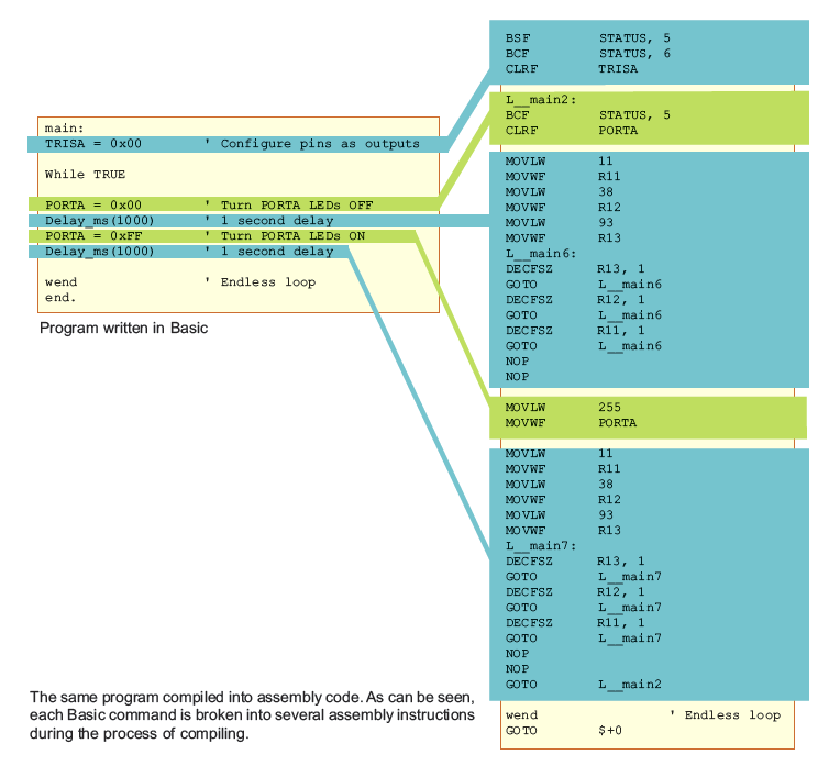
On the other hand, programs are always executed at high speeds and in most cases it is not necessary to know in detail what is going on within the microcontroller. Despite all good attributes of the assembly language, programmers have always needed a programming language similar to the language they use in everyday speech. Finally, high-level programming languages, including Basic, have been created. The main advantage of these languages is a simplicity of program writing. Several assembly instructions are now replaced by one statement in Basic. The programmer is not required to be familiar with the instruction set of the microcontroller in use any more. It is no longer possible to know how each statement is executed, but it doesn’t matter anyway. In case it does, the problem is solved by adding a sequence written in assembly language to the program.
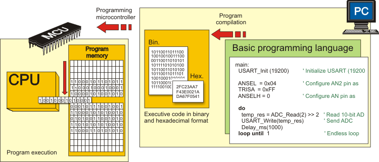
Similar to assembly language, a specialized program installed on the PC is in charge of compiling program into machine code. Unlike assembler, compilers for high-level programming languages create an executable code which is not always the shortest possible.
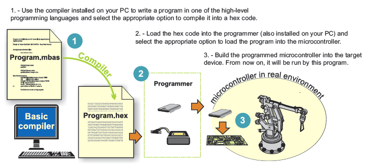
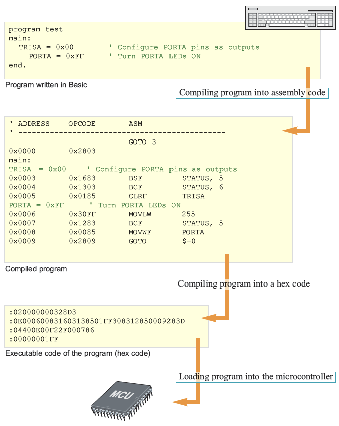
Figure above gives a rough illustration of what is going on during the process of compiling a program written in Basic into a hex code.
Here is an example of a simple program written in Basic:
ADVANTAGES OF HIGH-LEVEL PROGRAMMING LANGUAGES
If you have any experience in writing programs for PIC microcontrollers in assembly language, then you are probably familiar with the other side of the medal of RISC architecture - the lack of instructions. For example, there is no appropriate instruction for multiplying two numbers. Of course, there is a way to solve this issue owing to mathematics which enables you to perform complex operations by breaking them into a number of simple ones. Accordingly, multiplication can be easily substituted by successive addition (a x b = a + a + a + ... + a). And here we are, just at the beginning of a very long story... Still there is no reason to be worried about as far as you use one of the high-level programming languages, such as Basic, as the compiler will automatically find a solution to these and similar issues. Simply write a*b.
MPLAB IDE
MPLAB IDE is Microchip’s free, integrated toolset for the development of PIC® microcontroller and dsPIC® digital signal controller embedded applications. MPLAB IDE runs as a 32-bit application on MS Windows®, is easy to use and includes a host of free software components for fast application development and supercharged debugging. MPLAB IDE also serves as a single, unifi ed graphical user interface for additional Microchip and third-party software/hardware development tools. Moving between tools is easy, and upgrading from the free MPLAB SIM simulator to MPLAB ICD 3 In-Circuit Debugger or the MPLAB REAL ICE In-Circuit Emulator is effortless, since MPLAB IDE has the same user interface for all tools.
Download MPLAB IDE and use the MPLAB IDE Quick Start manual to discover how easy it is to create an application. Write code, build and assemble your project with MPLAB wizards, then test your code with the built-in simulator and debugger. Explore the capabilities of all Microchip microcontrollers. When you are ready to test your application, use a PICkit 3 or MPLAB ICD 3 to program a device and analyze your hardware, or choose a production-graded, universal MPLAB PM3 programmer to program your code. For the ultimate in analysis, rely upon the MPLAB REAL ICE in-circuit emulator to help find the toughest bugs and fine tune your application.
■ MPLAB SIM – High-speed software simulator features peripheral simulation, complex stimulus injection and register logging. MPLAB SIM executes your code and can be exercised with stimulus signals from files, from mouse clicks and from easily set up waveforms. The contents of variables and special function registers can be logged to a file for analysis.
■ Programmer’s Text Editor – Color-coded context easily shows typos and incorrect assembler and C statements. Full debugging is performed while in the editor window, including setting breakpoints, displaying variable values with mouse over and setting trace ranges.
■ Full-Featured Debugger – Watch windows show C structures and arrays, as well as all variables from C and assembler source. Step-over, step-into, step-out and run to cursor allow quick inspection of code operations.
■ Data Monitor Control Interface (DMCI) – Provides a graphical method to input and adjust software motor parameters. Plots can be used to show a time history of control variables so that the motor dynamic response can by analyzed. Useful for tweaking software parameters and visualizing historical data during debug sessions.
■ Version Control Support – For MS Source Safe, CVS, PVCS and Subversion.
■ Macro Assembler – For all current Microchip devices, with linker and librarian for building reusable code libraries. These can be used for assembly language programming and are also delivered with the Microchip C Compilers.
■ Graphical Project Manager – Source fi les can be instantly opened and edited, different optimizations can be applied to different source fi les and all project files are displayed in the project window.
PICkit 3
The PICkit 3 programmer/debugger (see Figure) is a simple, low-cost in-circuit debugger that is controlled by a PC running MPLAB IDE (v8.20 or greater) software on a Windows® platform. The PICkit 3 programmer/debugger is an integral part of the development engineer’s toolsuite. The application usage can vary from software development to hardware integration.
The PICkit 3 programmer/debugger is a debugger system used for hardware and software development of Microchip PIC® microcontrollers (MCUs) and dsPIC® Digital Signal Controllers (DSCs) that are based on In-Circuit Serial Programming™ (ICSP™) and Enhanced In-Circuit Serial Programming 2-wire serial interfaces. In addition to debugger functions, the PICkit 3 programmer/debugger system also may be used as a development programmer. The PICkit 3 programmer/debugger is not intended to be used as a production programmer.
The debugger system executes code like an actual device because it uses a device with built-in emulation circuitry, instead of a special debugger chip, for emulation. All available features of a given device are accessible interactively, and can be set and modified by the MPLAB IDE interface.
The PICkit 3 debugger was developed for emulating embedded processors with debug facilities. The PICkit 3 features include:
• Full-speed USB support using Windows standard drivers
• Real-time execution
• Processors run at maximum speeds
• Built-in over-voltage/short circuit monitors
• Low voltage to 5V (1.8-5V range)
• Diagnostic LEDs (power, active, status)
• Read/write program and data memory of microcontroller
• Erase of all memory types (EEPROM, ID, configuration and program) with verification
• Peripheral freeze at breakpoint
1.2.1 Lanyard Connection
A convenient lanyard connection is available on the programmer.
1.2.2 USB Port Connection
The USB port connection is a USB mini-B connector. Connect the PICkit 3 to the PC using the supplied USB cable.
1.2.3 Pin 1 Marker
This marker designates the location of pin 1 for proper connector alignment.
1.2.4 Programming Connector
The programming connector is a 6-pin header (0.100" spacing) that connects to the target device. See the pin out specification in Figure 1-2.
1.2.5 Indicator (Status) LEDs
The Status LEDs indicate the status of the PICkit 3.
1. Power (green) – Power is supplied to the PICkit 3 via the USB port.
2. Active (blue) – The PICkit 3 has connection to the PC USB port and the communication link is active.
3. Status:
Busy (yellow) – The PICkit 3 is busy with a function in progress, such as programming.
Error (red) – The PICkit 3 has encountered an error.
Reference : www.microe.com
www.microchip.com


No comments:
Post a Comment