There are many ways to achieve this. One of the simplest ways is to use a voltage to frequency conversion chip along with an analog temperature sensor such as LM335 or a thermistor, and then transmit the modulated frequency signal via an RF data link module. Alternatively, we can use a digital temperature sensor and sending the sensor readings over RF serial data link digitally. In this post I will stick with the first approach.

f=C0RntcRntc+R0Vcc=C1RntcRntc+R0
C0=Rs2 09
09 RLRtCt
1Rntc T
T
f=C11+C2T
T=C1fC2−1C2
#include
unsigned long frq;
float a = -165.0;
float b = 151735.0;
float GetTemp(float f)
{
return a + (b/f);
}
void setup()
{
Serial.begin(9600);
}
void loop()
{
FreqCounter::f_comp = 106;
FreqCounter::start(1000);
while (FreqCounter::f_ready == 0)
frq = FreqCounter::f_freq;
Serial.println(GetTemp(frq));
}
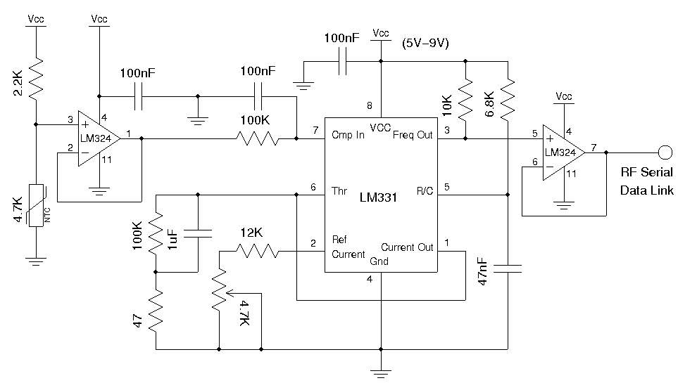
The following schematic shows the circuit design:
Here the 1/4 LM324 (or LM2902) forms a voltage follower to buffer the input voltage from the resistor-thermistor voltage divider, and the divider output is fed into an LM331 voltage to frequency converter. The LM331 portion of the circuit was taken directly from the reference design.
The capacitor at pin 5 needs to be adjusted so that the maximum frequency output from the oscillator is below the maximum bit rates supported by the RF link. The RF data transmitter I used has a maximum bit rate of 2400 bps and thus I used a 47nF capacitor and the oscillation frequency is around 700 Hz under room temperature.
The frequency output from LM331 is again buffered via another 1/4 LM324 (or LM2902) before feeding into the RF data link transmitter. This voltage to frequency circuit is arguably not the most accurate one and you could improve your accuracy by adding an op-amp integrator as illustrated in the datasheet, but for the temperature measurement application we are discussing here, this simple circuit is accurate enough.
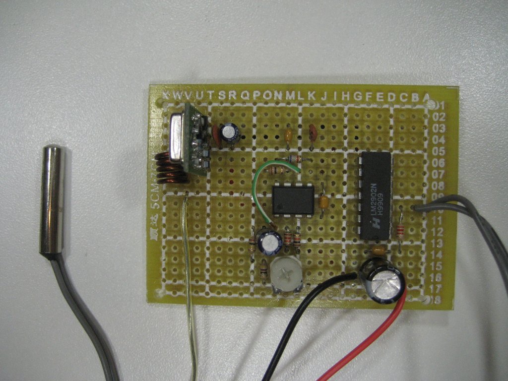
According to the LM331 data sheet, the timing components need to have very high stability in order to achieve a high level of accuracy and minimize frequency drift. The picture above shows the finished transmitter portion of the temperature sensor. Note that the power supply must be regulated in order to obtain accurate readings since it is referenced by the thermistor voltage divider.
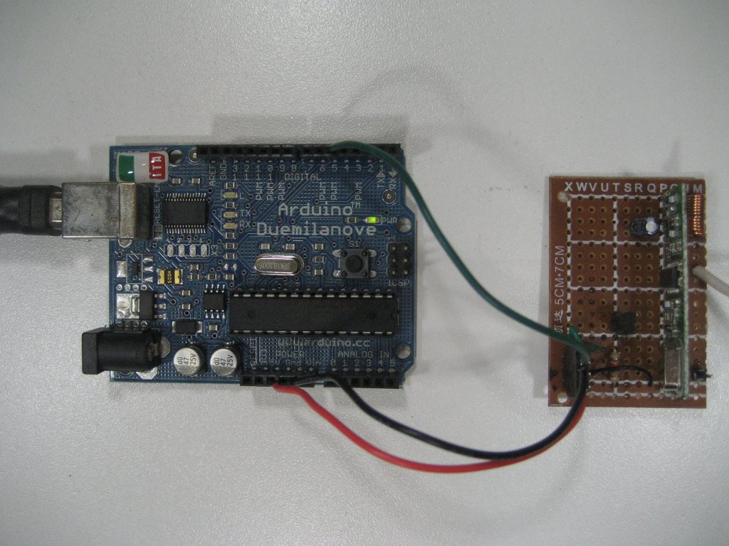
I could have built the receiver using another LM331 as a frequency to voltage converter and use the voltage readouts to calculate the temperature readings. But then I would need to use an A/D converter to convert the signal back to digital form in order to perform the calculation. To simplify the design, I used an Arduino MCU (ATmega328) to measure the frequency output from the RF data link receiver directly. The following picture shows the setup on the receiver end.
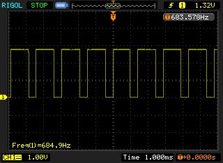
The oscilloscope capture below shows the output waveform from the receiver when the transmitter side is under room temperature.
With the transmitter and receiver working, now we need to convert the received frequency readings back to the temperature readings. Again, to help you understand how the calculation is done I have included the reference schematic below:
We know that the converter’s output frequency is a linear function of the input voltage at the voltage divider:
C0 is a constant that can be derived from the following equation according to the datasheet:
09RLRtCt
Since the temperature is roughly inversely proportional to the thermistor value within a small temperature range:
T
We can further simplify the frequency output to:
And thus we can derive the measured temperature as:
Although the two constants C1 and C2 can be determined by the theoretical values of the components, it is probably simpler to obtain them experimentally by measuring two or more frequencies at different temperature points.
Below is the Arduino code I used. The FreqCounter library I used can be found here. Note that parameters in the code are tailored specifically for the type of thermistor I used and they are also affected by the transmitter supply voltage (in my case the transmitter operates on 5V). You will need to re-calculate the parameters based on the equations I gave above.
#include
unsigned long frq;
float a = -165.0;
float b = 151735.0;
float GetTemp(float f)
{
return a + (b/f);
}
void setup()
{
Serial.begin(9600);
}
void loop()
{
FreqCounter::f_comp = 106;
FreqCounter::start(1000);
while (FreqCounter::f_ready == 0)
frq = FreqCounter::f_freq;
Serial.println(GetTemp(frq));
}
1 comment:
excellent work!!
you can install this part in the remote of each and every AC so that the temperature can be be detected at that location.
how are you going to make the rf circuit?
even i a working on a project, so please let me know.
Post a Comment