Search

Sunday 29 April 2012

Making PCB at Home : Perfectly Working

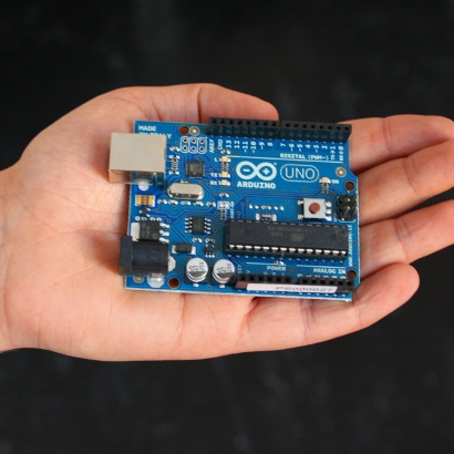
While making PCB's at home isn't particularly difficult, If you've done any kind of building at all, you can appreciate how much difference it makes to stuff a pre-printed PCB versus hand wiring on bread board or GPB.
All you Need is:
  1. PCB Designing Software
  2. Simple Copper Plated PCB    Cost: RS 100 Max
  3. Nearest Computerized Car Number Plate Maker..!!    Cost: Can be any 50-500 RS.
  4. Etching Solution    Cost: Rs.90 per 500GMS
  5. Water
  6. Container
  7. Small Hand Drill    Cost Rs.150

First of all software I use to design the PCBs is Protel DXP, or you can use EAGLE PCB. Protel DXP is not Free ware, you have to purchase  the licence to use that.
EAGLE is free, put out by CadSoft.You can download for free either for a Linux or Windows version of this layout tool, whose only limitation is a maximum of one schematic page and about a 2.5x4" PCB size.

For the demostration I'm going to show you simple bridge circuit, with Protel DXP.
Now,
Make the Schematic file in the Protel DXP but putting components in the schematic capture,connect each components and after adding PCB to the project, I will import that whole schematic in to the PCB.

Now the PCB Viewer is opened, and arrange the components and route the whole PCB using Auto routing.

Now what to have to do is,Go to File> Print out the PCB file using the virtual PDF installed on you machine and save it to the .PDF flie.

STEPS TO MAKE IT HARD:
  1. After printing this file to the .PDF format, convert that file to .JPEG using Adobe Photoshop(PS) also do it "X - Mirror" in PS. Save it as .JPEG. Take this .JPEG file and the perfect size of your PCB file in mm (That can be done be CTRL+M in Protel DXP) to the nearest Computerized Car Number Plate maker.
    Making it X-Mirror is very important as you have whole track in the bottom layer.
  2. Give this JPEG file and let him cut through his computerized Plotter on a thick sticker and stick that sticker to your copper plated PCB. 
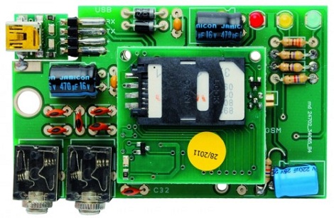
  3. See how my circuit looks like.(I have used another circuit down here, but yours will be nearly same)
  4. Etching Safety Precautions :
    1. Wear Hand glows while putting/taking out circuit in/from solution, as the solution heats up too much when you add FeCl3 in to water, and also can harm your skin.
  5. The solution you have to use is FeCl3(two table spoons for small size PCB) + some hot water(not too much!!), which is used in the laboratories. It will not be a nightmare if you disliked the Chemistry..!! (sorry have taken another different image, picture is just to demonstrate you the process of making PCB, FYI : it's from my LAB only, not copied from the internet.!!).Put it in this solution for whole day in one container.
After putting it in the Etching Container for whole day, take it out, wash your circuit and peel off that sticker. 


This is the image after the whole process.


Drill the holes at your desired places. Mount the components.
Enjoy Electronics...!!!

Tuesday 24 April 2012

Printing PCBs on a junked Epson printer


When it comes to making PCBs at home really quickly, there’s not much to improve upon with Ryan‘s bodged up Epson printer that prints an etch mask directly on a piece of copper clad board.
Like most of the direct to copper PCB printer conversions we’ve covered ( 1, 2, 3 ), [Ryan]‘s build relied on an Epson printer and Mis Pro yellow ink. The Mis Pro ink is one of the most etch-resistive substances that can be shot out of an inkjet printer, and Epson printer cartridges use a piezo pump that is perfect for squirting ink out on command.
After tearing the printer apart and lifting the print head a bit, [Ryan] needed a proper feed system to control where on the copper he was printing. He managed to make a board carrier out of a sheet of aluminum. By taping down the copper clad board, everything seems to work phenomenally.
After the break you can check out how fast [Ryan] can print out a fully etch-resisted PCB. It’s not improbable that he could produce a few dozen boards an hour; something our toner transfer PCB production method would kill for...!!!

Finding your keys with Bluetooth


Do you misplace you keys everyday..??
To solve this problem, Doragasu created a small Bluetooth-enabled key fob that is able to remotely sound an alarm when commanded to by a cell phone.
The case and LiPo battery of [doragasu]‘s project comes from a small photo frame key fob. The LCD display and PCB of the photo frame were tossed aside for a future project, and the design of the circuit started. The Bluetooth buzzer key fob is based around an MSP430 microcontroller because of their extremely low power requirements.
On the software side of things, [doragasu] built a J2ME app to connect to the key fob and turn the buzzer on. His app is portable to any Android phone, and versions can be ported to Windows, OS X and iOS devices.
How does it work? Well, [doragasu]‘s wife sometimes forgets to charge her key fob, rendering the whole project useless. There are ideas for  updating the device to a Bluetooth 4.0 Low Energy device

Monday 23 April 2012

Google’s SKPR Bot, not for arachnophober.


Google’s Maker Faire exhibit space is swarmed with robots, androids. Amidst some cool bipeds and Segway-balancers, our inner sci-fi nerd was most smitten with this hexapod design, which they’ve dubbed SKPR Bot. The “Skipper” is on hand to showcase the ease of various Google technologies: SketchUp, Android OS and theAndroid Open Accessory Development Kit. The whole project came together in less than six weeks. 
18 servos are mounted to a framework designed in SketchUp and laser-cut byPonoko. The low-level servo PWM control is handled by the Dev Kit (essentially a rebadged Arduino Mega, as we’ve seen), while an Android OS phone provides a slick GUI and handles all the inverse kinematics calculations required as the robot takes each step. The coolest bit is that it’s all up for grabs. At this moment you’ll have to scrounge around the ’net a bit to find the plans and code, but some time post-Faire they plan to bring everything together at the SKPR Bot site.


Low-cost, low-bandwidth wireless Arduino to Android communications


android_nfcJoe was experimenting with his Arduino when he started thinking about how he could get it to communicate wirelessly with his Android phone. Bluetooth is an option, but it requires some extra components, and Google’s ADK works as well – just not wirelessly.
Instead, he thought it would be neat to see if he could get the two devices to communicate with a simple magnetic coil. He constructed a small 1cm diameter coil, connecting it to the Arduino via a resistor and diode. Using the Android Tricorder app, he was able to locate his phone’s magnetometer, after which he ran some tests to narrow down the best sample rate and frequency range for communications.
To transfer data between the two devices, he had to bit bang the signal in software, since the Arduino’s UART has a lower limit far faster than the 7 bps data rate he was able to achieve with the magnetometer.
While his wireless Arduino to Android bridge isn’t likely to win any awards for throughput, it is a great proof of concept project.

Thursday 19 April 2012

Speech-Controlled Arduino Robot with Xbee Module

We all dream of having appliances and machines that can obey our spoken commands. Well, let’s take the first step towards making this happen.  In this second iteration of Carlitos’ Projects, we are going to build a speech-controlled Arduino-based robot.
Speech Controlled Arduino Robot
You may be thinking that making such a robot must be a very complex task. After all, humans take many years before they can understand speech properly. Well, it is not as difficult as you may think and it is definitely lots of fun. The link below illustrates how to make your own speech-controlled Arduino rover.

Go to this link.

Wednesday 18 April 2012

Driving Vertical Towers : Surveying for High-rise Structures

The construction of iconic towers such as the 828-metre high Burj Khalifa (formerly Burj Dubai), officially inaugurated on 4th January 2010 in Dubai, poses many challenges to surveyors. Tall towers may bend and sway in the wind, with cranes and other loads. Ideally, such motion should centre on the as-designed main axis, so that in the absence of load the tower stands precisely vertical, but deviations occur as a result of raft settlement, concrete shortening and construction tolerances. The author presents a new, patented measurement system capable of driving the highest towers in an exactly vertical direction.

To guarantee the precise upward thrust of a tower along the vertical during construction, complete control must be maintained of the position of each new element erected on top of the existing core walls. Such new elements, and hence formwork structures, must be precisely positioned with respect to the main axis of the design reference frame, which is defined as the vertical positioned in the centre of tower. This means that the position of the formwork structures at the top of the tower must be continuously measured during erection of the building.

Anomalies
Under ideal conditions the coordinates of survey marks as measured refer to the design frame (top), but stresses introduce anomalies shown as red vectors (bottom).The coordinates, computed from the measurements, should refer to the main axis very precisely and reliably. However, anomalies arise from movement due to wind, cranes, sun radiation and other loads, and vibrations within the tower (Figure 1). Conventional methods for monitoring tall towers, such as optical plumbing, are incapable of compensating for such anomalies, and this is an intolerable drawback when the towers are super high-rise, such as the Burj Khalifa in Dubai. To control such towers, Leica Geosystems developed and proof-tested a new measurement system based on GNSS (GPS and Glonass) combined with high-precision inclination sensors and total-stations. The surveying procedure, called Core Wall Control Survey System (CWCSS), has been applied to the Burj Khalifa in Dubai, UAE; the Al Hamra tower in Kuwait; the Landmark tower in Abu Dhabi; and other high-rise buildings around the world, and has been patented under International Publication Number WO 2007/080092 A1.

Active GCPS
GNSS receiver acting as active ground control point during construction of the Landmark Tower in Abu Dhabi.Core walls are constructed bit by bit, one on top of the other. Each core wall element consists of several concrete pours. The placement of the formwork structure on top of existing core walls should be done very precisely, determined from the position of previously placed elements. For this purpose control points, materialised, for example, by nails, have to be set in the top of the concrete. The basic task of the surveyor is to determine the coordinates of these control points and to compute and stake out the position of the formwork structure in a design reference system based on the main axis of the tower. Basically, the work consists of measuring angles and distances with a high-grade total-station positioned on a ground control point (GCP). In the new CWCSS system the total-station remains the main instrument, providing as it does distances and angles to compute the coordinates of control points and any other mark or object in the structure. On most construction sites surveyors carry out their work in the midst of a tangle of steel and other obstructions, and beneath or beside materials lowered by cranes; working areas are congested with materials, equipment and men and, of course, working at height requires special safety measures. Under such conditions, GCPs on which the total-stations can be positioned are scarce. So the CWCSS system is based on positioning total-stations from measurements to three or four GNSS (GPS + Glonass) receivers to which 360° reflectors are attached beneath the antenna (Figure 2).
Precise positioning of total-station from measurements to GNSS receivers equipped with reflectors and operating in differential mode using a continuous operating reference station.
These act as active ground control points for setting up the total-station at any stage of construction (Figures 3 and 4). In Figure 3 the red circles indicate the positions of the control points, and the blue triangle that of the total-station. The GNSS antennas should be placed such that the lines of sight between antenna and satellites are not obstructed by constructions and buildings, while reflection and diffraction of the satellite signals should be carefully avoided. Because very precise coordinates can only be determined in differential GNSS mode, a continuously operating reference station has to be established, preferably located outside the construction venue (Figure 5).

Inclination Sensors
Schematic overview of the concept of Active GNSS Ground Control Points.To determine the offset caused by movements of the tower, dual-axis precision inclination sensors, which measure the exact offset from the vertical of the tower, are installed at ground level and about every given number level above. Mounted on the core wall along a vertical line, these measure any variation in tilt of the main axis of the tower. The offsets calculated from these measurements are used to correct the coordinates of the control points as measured by the total-station, ensuring that the building is constructed as straight element, pointing precisely vertically, regardless of movement. To calibrate the inclination sensors, tilt values can be compared with measurements gained through vertical laser plummet beams passing through holes made on different levels, the method used for the Burj Khalifa, or using a motorised high-precision dual-axis inclination sensor, as for the new Ryiad Tower in Saudi Arabia.

Continuous Operating Reference Station in Dubai.Gravity Vertical
A network of marks made to identify GCPs and used to set up the total-stations must be established around the construction area to ensure a proper design reference frame to which all measurements can be referred. These marks need protecting and regular re-survey during the construction process (Figure 6). GNSS receivers, total-stations and inclinometers must all refer to the design reference frame. Since GNSS coordinates refer to the ellipsoidal WGS84 system, these will have to be transferred to the design reference frame. The vertical defined by gravity, as visualised by a plumb-line, differs from the ellipsoid normal. This introduces a bias which will affect vertical alignment of the construction. Applying corrections is of the utmost importance, since the gravity vertical, as the main reference for the main axis of the tower, is the most sensitive component.

Benefits
The CWCSS method enables the surveyor to continue his control measurements even when the building moves off centre, since the network of dual-axis inclination sensors provides continuous precise information on tilt variation. Combining tilt values with measurements from other instruments, such as wind-speed sensors and t
hermometers, enables derivation of a relationship between tilt and loads due to weather and other sources. 
Re-survey of a ground control point using differential GNSS.
Establishment of such relationships provides valuable information for explaining the causes of movement and understanding the behaviour of the building. It also enables the identification of and compensation for systemic bending in one direction by adapting placement of elements on top of finalised parts during the construction phase. Precise positioning of formworks can thus be realised without the need to sight to external GCPs, a procedure which becomes increasingly difficult as erection of the building progresses. Control surveys can be completed within a short time span, improving productivity, and instruments do not need to be levelled, important in the presence of movement and vibration.

Concluding Remarks
CWCSS provides an effective method for determining coordinates of points during driving the highest buildings in a vertical direction. However, determination of the vertical component is very sensitive and should be checked and double-checked using conventional levelling procedures in addition to the CWCSS system. The network of inclination sensors can be kept operational after completion of the building for long-term monitoring of the behaviour of the tower. A GNSS antenna can also be kept running on the top of the tower to provide deflection information.

Tuesday 17 April 2012

Arduino based Bluetooth wristwatch

The watch is built around an Arduino Pro Mini, a scavenged Nokia LCD, and aBlueSMiRF Gold. The Bluetooth connects to a Nokia N900 with a little Bluetooth client app. Designer also wrote a small GUI for the watch’s LCD display. Afterwards, he was able to display missed calls, new email, and is now working on support for changing songs on his N900′s media player.
Admittedly, a little work needs to be done on the enclosure. Still, the potential for this watch is much greater than the iPod as a watch project we saw last year. Right now, we’re thinking about what could be added to [Ahmet]‘s watch. An accelerometer would probably be on the top of our list, but if you have any ideas feel free to leave them in the comments.

Monitoring water levels with a Parallax Ping sensor


This device built by Danilo uses a Parallax Ping sensor instead. If the sensor is placed at the top of a well, cistern, or other water container, it can accurately calculate the height and volume of the fluid inside. This is done by using the Ping’s readings in conjunction with a few values already known to the user, namely the dimensions of the container.
arduino_parallax_ping_water_level_sensorWhen you need a mechanism to detect the water level within a container or tank, you have several different options. Most people opt for a simple float or probe that sits in the water, while others use optics to sense when the water is reaching an undesired level.
In his implementation, the readings are relayed to a simple LCD panel for easy viewing, and a small piezo speaker is used to sound an alarm when the water level reaches a predefined threshold. This sort of measuring device can be quite useful in situations where a contact-based sensor would be subject to chemicals and corrosion, or where contamination is a concern.

Monday 16 April 2012

555 timer-based charge controller for solar and wind systems


555_charging_controller_circuitSeveral years ago Michael Davis built a charge controller for his wind turbine and published his construction plans online. This build became quite popular, especially among people that live in remote regions. He states that he is flooded with email each day with questions about his charge controller from people trying to troubleshoot its construction or from people who are unable to source the proper parts.


In order to make things easier for people, he decided to revisit his controller design to see what could be improved, and more importantly, what could be removed. The revision was shelved for awhile, but while in the process of working on another project, he realized that most of his original circuit could be easily replaced with a 555 timer. Since the 555 chip is so ubiquitous, he figured it was a fantastic way to simplify his charger, even if he wasn’t using the chip in the manner for which it was originally designed.

This 555 based solar charge controller project has won first place in the Utility Category of the 555 Design Contest.

Visit his controller design.

Sunday 15 April 2012

Using diodes and transistors as solar cells


When you get down to it, solar cells aren’t much different from the diodes and transistors in your parts drawers or inside your beloved electronics. They’re both made of silicon or some other semiconductor, and surprisingly can produce electricity in the presence of light. Here’s two semiconductors-as-solar panel projects that rolled into the tip line over the past few days.
[Steven Dufresne] cut open a 2N3055 power transistor to expose the semiconductor material to light. In full sunlight, he was able to produce 500 millivolts and 5.5 milliamps. In other words, he’d need around 5000 of these transistors wired up to turn on a compact fluorescent light bulb. A small calculator has a much lower power requirement, so after opening up five transistors he was able to make a solar-powered calculator with a handful of transistors.
[Sarang] was studying solar cells and realized a standard silicon diode is very similar; both are p-n junctions and the only real difference is the surface area. He connected a1N4148 to a multimeter and to his surprise it worked. [Sarang] is able to get about 150 millivolts out of his diode with the help of a magnifying glass. While he doubts his diode is more efficient than a normal solar cell, he thinks it could be useful in low-cost, low power applications. We’re thinking this might be useful as a high-intensity light detector for a solar cooker or similar.
After the break, you can check out the videos [Steven] and [Sarang] put up demonstrating their solar cells.

Power Without the Cord for Small Devices


Cell phones and flashlights operate by battery without trouble. Yet because of the limited lifespan, battery power is not a feasible option for many applications in the fields of medicine or test engineering, such as implants or probes. Researchers have now developed a process that supplies these systems with power and without the power cord.
Technology that can be worn on a belt
For more than 50 years, pacemakers have set the rhythm for many hearts. The engineering of microelectronic implants has since advanced by leaps and bounds: they have become ever-smaller and more technologically sophisticated. The trend is moving toward miniaturized, intelligent systems that will take over therapeutic and diagnostic functions. For example, in the future implantable sensors will measure glucose levels, blood pressure or the oxygen saturation of tumorous tissue, transmitting patient data via telemetry. Meanwhile, medication dosing systems and infusion pumps will be able to deliver a targeted release of pharmaceutical substances in the body, alleviating side effects in the process.

The picture may be used for editorial purposes only. It is protected by copyright. The use is free of charge if the reference is mentioned. With the aid of magnetic coupling, power can be transmitted wirelessly from a transmitter to a receiver module. The prototype with the transmitter can be attached to the belt. (Credit: © Fraunhofer IKTS)
All these solutions are composed of probes, actuators, signal processing units and electronic controls -- and therein lies the problem, too: they must have a power supply. Batteries are usually ruled out because of their limited durability -- after all, implants stay inside the body for years. Currently, radio wave-based (HF) and inductive systems are most commonly in use. However, these exhibit differences in efficiency based on location, position and movement and are also often limited in range. Soon, a new power transfer system should circumvent the limitations of previous methods. Researchers at the Fraunhofer Institute for Ceramic Technologies and Systems IKTS in Hermsdorf succeeded in wirelessly transmitting power from a portable transmitter module to a mobile generator module -- the receiver.
The cylindrical shaped transfer module is so small and compact that it can be attached to a belt," says Dr. Holger Lausch, scientist at IKTS. The transmitter provides an electric current of over 100 milliwatts and has a range of about 50 centimeters. As a result, the receiver can be placed almost anywhere in the body. "With our portable device, we can remotely supply power to implants, medication dosing systems and other medical applications without touching them -- such as ingestible endoscopic capsules that migrate through the gastrointestinal tract and transmit images of the body's inside to the outside," says Lausch. The generator module can be traced any time -- regardless of power transfer -- with respect to its position and location. So if the generator is located inside a video endoscopy capsule, the images produced can be assigned to specific intestinal regions. If it is placed inside a dosing capsule, then the active ingredient in the medication can be released in a targeted manner.
Energy can pass through all non-magnetic materials
How does this new, already patented system work? In the transfer module, a rotating magnet driven by an EC motor generates a magnetic rotary field. A magnetic pellet in the receiver connects to the alternating exterior magnetic field and as a result, is set in rotation itself. The rotational movement is transformed into electricity, thus the power is produced right in the generator module. "With magnetic coupling, power can be transported through all non-magnetic materials, such as biological tissue, bones, organs, water, plastic or even a variety of metals. Moreover, the magnetic field produced has no harmful side effects on humans. It doesn't even heat up tissue," says Lausch, highlighting the advantages of the system.
Because the modules available as prototypes are scalable in terms of range, size and performance capacity, they can be used for more than medical technology applications. They can also supply power wirelessly to hermetically sealed sensors -- such as those inside walls or bridges. This makes them suitable for use in mechanical engineering and plant construction and in the construction industry. Other conceivable applications include the charging of power storage units and activation of electronic components.
Using a hip implant as a demonstration tool, Lausch and his team will demonstrate how their wireless power transmission system functions at the Hannover Messe from April 23-27. In this case, the technology electrically stimulates the ball-and-socket joint to stimulate the growth of cartilage and bone cells.

Saturday 14 April 2012

Free formed circuit protected by a brick of crystal clear resin


He deserves a lot of credit for working out a visually pleasing way to mount each component. There wasn’t any type of substrate used, but a few lower gauge wires were picked as the rails and they add some mounting stability. Before casting, he took the case of each of the three jacks apart and sealed the seams with some of the casting resin to prevent the final pour from filling them up.
The look of this crystal clear resin brick is pretty amazing. Rupert Hirst decided to encase his amplifier circuit in a block of polyester resin. We just hope he got everything in his circuit right because there’s no way to replace any of those parts now!
Eagle CAD was used to design the mold. He printed it out on some card stock, then used a hobby knife to cut the pieces out and super glue to assemble them. A second layer of super glue was run on each seam to ensure they’re water tight. After the casting was made [Rupert] spent plenty of time sanding, routing, and polishing the brick to achieve this look.
This makes us wonder about heat dissipation. Do you think it will be a problem? Tells me what your opinion by leaving a comment.

Monday 9 April 2012

Arduino

Arduino hardware is programmed using a Wiring-based language (syntax and libraries), similar to C++ with some slight simplifications and modifications, and a Processing-based integrated development environment.

Arduino is a popular open-source single-board microcontroller, descendant of the open-source Wiring platform,designed to make the process of using electronics in multidisciplinary projects more accessible. The hardware consists of a simple open hardware design for the Arduino board with an Atmel AVR processor and on-board input/output support. The software consists of a standard programming language compiler and the boot loader that runs on the board.

Official hardware

Thirteen versions of the Arduino hardware have been commercially produced to date:[4]The original Arduino hardware is manufactured by the Italian company Smart Projects. Some Arduino-branded boards have been designed by the American company SparkFun Electronics.
  1. The Serial Arduino, programmed with a DE-9 serial connection and using an ATmega8
  2. The Arduino Extreme, with a USB interface for programming and using an ATmega8
  3. The Arduino Mini, a miniature version of the Arduino using a surface-mounted ATmega168
  4. The Arduino Nano, an even smaller, USB powered version of the Arduino using a surface-mounted ATmega168 (ATmega328 for newer version)
  5. The LilyPad Arduino, a minimalist design for wearable application using a surface-mounted ATmega168
  6. The Arduino NG, with a USB interface for programming and using an ATmega8
  7. The Arduino NG plus, with a USB interface for programming and using an ATmega168
  8. The Arduino Bluetooth, with a Bluetooth interface for programming using an ATmega168
  9. The Arduino Diecimila, with a USB interface and utilizes an ATmega168 in a DIL28 package (pictured)
  10. The Arduino Duemilanove ("2009"), using the ATmega168 (ATmega328 for newer version) and powered via USB/DC power, switching automatically
  11. The Arduino Mega, using a surface-mounted ATmega1280 for additional I/O and memory.
  12. The Arduino Uno, uses the same ATmega328 as late-model Duemilanove, but whereas the Duemilanove used an FTDI chipset for USB, the Uno uses an ATmega8U2 programmed as a serial converter.
  13. The Arduino Mega2560, uses a surface-mounted ATmega2560, bringing the total memory to 256 kB. It also incorporates the new ATmega8U2 (ATmega16U2 in revision 3) USB chipset.


A typical first program for a microcontroller simply blinks a LED on and off. In the Arduino environment, the user might write a program like this:

#define LED_PIN 13
 
void setup () {
    pinMode (LED_PIN, OUTPUT);     // enable pin 13 for digital output
}
 
void loop () {
    digitalWrite (LED_PIN, HIGH);  // turn on the LED
    delay (1000);                  // wait one second (1000 milliseconds)
    digitalWrite (LED_PIN, LOW);   // turn off the LED
    delay (1000);                  // wait one second
}

Measuring the capacities of different battery brands


Being the smart consumer he is, [Denis] usually looks at the price per pound when comparing similar products at the grocery store. When it came time to buy a few AA batteries, he didn’t have any data to go on. To solve his little conundrum, [Denis] decided he would test several brands of batteries and see which one gives him the most bang for the buck.
After bringing home a haul of a dozen different brands of AA cells, [Denis] broke out the Arduino and starting designing a circuit. To test how much energy each brand provides, the Arduino measures the voltage across a load every second until the battery reaches 0.2V. The elapsed time, as well as the voltage, Watt hours, Joules, and ambient temperature are logged on an attached LCD screen and sent over a USB serial link to automate the data collection process.
What’s the verdict? Unsurprisingly, words like ‘super,’ ‘max,’ and ‘ultra’ didn’t connotate a better battery. The best bang for the buck came from an off-brand called RS Power Ultra. The worst battery was the Panasonic Evolta cells that came in at about $1.50 USD per watt-hour.
If you’d like to verify [Denis]‘ work, all the code is up on Github along with the schematic.

Saturday 7 April 2012

The best LED cube build I’ve ever seen


 8x8x8 RGB LED cube is the best I’ve ever seen.
To start his build, [Nick] built a simple 4x4x4 cube as a proof of concept. The baby cube worked but the fabrication process got him thinking. Instead of building his monster LED cube in layers from the bottom up, he would need to build columns from left to right. After the construction of a jig, soldering eight panels of 64 LEDs, and buying a new soldering iron tip, [Nick] had a beautiful assembled LED cube. The only thing missing was the electronics.
Most of the LED cubes we’ve seen use the TLC5940 LED driver for hardware PWM, [Nick] decided to go with the simpler but more familiar STP16 chip. After hooking up his huge LED driver board up to a chipKIT Uno, the 80 hours of programming began.
In the end, [Nick] built the best LED cube we’ve seen (even though it isn’t the largest) and put together one of the best build logs in recent memory.

A simple project to get you started with the Android ADK


The prerequisites for this project are a bit beyond a simple breadboard and a few ICs, requiring an $80 Android ADK board to go along with your phone and Arduino. If your focus is going to be on interfacing your phone with microcontrollers however, it’s purchase you’ll make sooner than later anyhow.
simple-adk-exerciseIf you just got your hands on a shiny new Android phone and are looking for a fun project to try out, you might want to check out this simple Arduino exercise that [Mike Mitchel] put together. Everyone needs a starting off point for hacking, and [Mike] thought that combining and Arduino and Android handset together for the purpose of temperature sensing and light metering would be a great place to begin.

The setup is pretty simple as you might expect. A photocell and TMP36 temperature sensor are connected to the Arduino, then with a bit of code and USB host magic, the Android app shows the temp and amount ambient light present in the room.

GSM modem means wireless serial connections


By now, most of us have seen have seen one of those GSM to wi-fi hotspot bridges. They’re interesting devices, and being able to carry a small wireless router with you at all times is very handy. Surprisingly, we haven’t seen many builds featuring these portable wireless hotspots, something probably due to the effort in breaking out a serial connection on these devices. The people at Open Electronics decided to build their own small serial-enabled cell phone modem, a boon to someone wanting a serial connection to any place with a cell tower.
The Open Electronics GSM/GPRS/GPS modem includes a header for an FTDI USB serial chip and a GSM module. Plug one into your computer and after a few short commands into a terminal, you’ve got a serial connection to nearly anywhere in the world.
The cost of the setup is a little high – around 5000 INR – and you probably should buy more than one so you can also receive data. While it is more expensive than the XBee wireless boards we see often, this GSM modem isn’t limited to the 300 foot range of the XBee. We’ll probably see this in a high altitude balloon before too long.

Wednesday 4 April 2012

Pretty Cool Robot Design


Skills are all that’s needed to solve a problem. Take this four-wheeled robot as an example. [Michal Zalewski] wanted it to be omnidirectional but wasn’t very satisfied with the concept of mecanum wheels and the like. So he designed a chassis with wheels at each corner that can pivot as one to change orientation. The image may look like a rendering at first glance, but this is actually the physical prototype. 

Tuesday 3 April 2012


You know how to whistle don’t you? You just put your lips together and blow. But do you know how to make the electronics around you react to your whistled commands? Well [Befi] figured out a system that allows him to assign a whistled command to various home electronics.
He’s using a set of RF remote control outlets to switch power to various devices like a desk lap, or a turn table. The board you see in the image above is the remote control that came with the system, but that chip is an ATmega8 which he added to give round-about USB connectivity using a serial-to-USB converter. The technique is simple enough that we’d bet you can get this to work with an ATtiny2313 and the V-USB project but that’s another story.
The additional piece is the use of embedded Linux to detect and process whistled commands. In the video after the break [Befi] explains that he’s using a Dockstar along with a microphone to capture audio input. It uses a Fast Fourier transform algorithm to process the clip and pushes commands to the remote control after processing is complete.

DrummerBot joins the jam session when your bandmates are busy


drummerbotHis DrummerBot is driven using an Arduino, which is tasked with controlling the 8 servo motors that the bot has at its disposal. The bot’s drum set is composed of a variety of items from fan motors to pot lids and more. [Steffest] wanted the ability to produce the maximum variety of sounds possible, so most of the servo motors are driven in two directions allowing the bot to strike more than one item with each “arm”.
It seems that more often than not, Steffest finds himself inspired to rock out on his guitar without a percussion section to back him up. Like any enterprising hacker/musician would be wont to do, he built a robotic drummer to join in when he got the urge to play.
[Steffest] is a big fan of interfacing physical objects with a web interface, so he built a simple HTML based sequencer that allows him to program the robot from his phone. Once the sequencer is programmed, the DrummerBot can be launched into action with the simple press of a button.

Monday 2 April 2012

Updating your workspace for more organized and efficient hacking


workspace-upgrade
If you’ve ever looked at one of [Todd Harrison’s] teardown or how-to videos closely, you would likely notice that his work bench looks like a standard hacker workspace. While we all try to keep our work areas clear of clutter, it’s not uncommon for components to pile up, cords to tangle, and things to get messy. [Todd] decided it was time to get a bit more organized, so he recorded a video showing how he went about the process.
Part of [Todd’s] work revolved around adding shelves to his bench so that he didn’t have measurement equipment stacked on top of one another. He also spent a good amount of time adding 30 additional plug sockets to his work space, replacing the single socket he had been struggling with for years.
Obviously this is not really a hack in and of itself, though this sort of reorganization is an important to efficient hacking all the same. We like the fact that [Todd] took the time to explain his process and materials in great detail – it will no doubt be helpful to those new to hacking.

Open source tracking system gets a Kickstarter


open-source-tracker
Many of the hacks featured here inspire others to build on the creator’s work, and on occasion the positive feedback brings the hack to market.
one original tracking device was powered by an Arduino, which monitored an accelerometer and GPS sensor, reporting coordinates and movements to his mobile phone on demand. so one person combined the disparate components together on a single board, and started a Kickstarter for the project.
Aside from his original purpose of tracking stolen goods, he lists off an array of other uses, such as tracking the driving habits of your newly licensed teen, geofencing objects in certain areas and more.
If an SMS controlled all-in-one tracking system is something you might be interested in, check out his Kickstarter, or take a look at the documentation and build one of your own.

Whether grasping Easter eggs or glass bottles, this robotic hand uses tact

 It may be difficult to imagine, but pouring juice into a plastic cup can be a great challenge to a robot. While one hand holds the glass bottle firmly, the other one must gently grasp the cup. Researchers at Saarland University together with associates in Bologna and Naples have developed a robotic hand that can accomplish both tasks with ease and yet including the actuators is scarcely larger than a human arm. This was made possible by a novel string actuator, making use of small electric motors to twist strings. The robotic hand is thus powerful yet delicate and could one day be deployed as a helper around the house or in catastrophic scenarios.
"When robots help around the house or should save people from a burning building, they need to have hands which can grasp with strength but at the same time gently," explains Hartmut Janocha, Professor of Process Automation at Saarland University. The challenge lies in trying to make the necessary technology fit within the robotic arm such that it does not differ significantly from a human arm in terms of size and form. „We came up with a simple, yet extremely effective idea: using strings that are twisted by small, high-speed motors, we are able to exert high tensile forces within a compact space," explains mechatronic researcher May. The sensorised and controlled robotic hand is able to touch diverse objects, to grasp and lift them and place them gently in a new position. Chris May demonstrated this in Karlsruhe with a delicate Easter egg and a heavy glass bottle."We wanted to impart our robotic hand with a broad spectrum of human traits. Its artificial muscles should be able to deliver enormous forces by simple and compact means," explains Chris May, scientist at Saarland University's Laboratory of Actuation Technology. The robotic hand was recently presented during a meeting at the Forschungszentrum Informatik in Karlsruhe. It is an example of some of the new steps taken in robotic research within the scope of the European project DEXMART. Over the past four years international scientists developed various concepts, especially focussed on increasing the versatility with which two-arm robots can be implemented. The European Union sponsored the research consortium to the sum of 6.3 million Euros.
Extremely strong polymer strings enable the Saarbrücken researchers to lift a five kilogram load by 30 mm within a split second, making use of a small electric motor and a 20 cm long string. „Each robotic finger, which like a human finger is composed of three segments, can be controlled precisely by means of the individual tendons ," describes Chris May the novel miniature actuator. The mini electric motors run at high speed and a small torque on the order of five Newton-millimetres. „The capability of the robotic hand is so near to that of humans that the vision of robots as personal assistants in the household, in the operating room as well as in industrial settings is becoming ever more realistic. We presume that the combination of small electric motors with twisted string is interesting for other applications as well," the researcher reckons.