Search

Wednesday 27 June 2012

Taking a dump from some old hardware


NYC Resistor shows you how to have some fun with electronics from the junk bin.Their post called The Joy of Dumping encourages you to look around for older memory chips and see what they’ve been hiding away for all these years.
I found this post when I was searching some stuff for my project work.
The targets of their hunt are EPROM chips. Note the single ‘E’. These are Erasable Programmable Read-Only Memory chips, and predate EEPROM which adds “Electrically” to the beginning of the acronym.  You used to use a UV light source to erase the older types of memory. In fact we’ve seen some EPROM erasers as projects from time to time. These shouldn’t be too hard to find as they were prevalent as cheap storage back in the 1980′s.
If the quartz window on the top of the chips has been shielded from ambient UV light, you should still be able to read them and it’s as easy as hooking up your Arduino. Is it useful? Not really, but it still can be neat to interface with what might otherwise never make its way back out of the junk box.

Thursday 14 June 2012

Wireless Temperature Sensor

There are many ways to achieve this. One of the simplest ways is to use a voltage to frequency conversion chip along with an analog temperature sensor such as LM335 or a thermistor, and then transmit the modulated frequency signal via an RF data link module. Alternatively, we can use a digital temperature sensor and sending the sensor readings over RF serial data link digitally. In this post I will stick with the first approach.


The following schematic shows the circuit design:
Here the 1/4 LM324 (or LM2902) forms a voltage follower to buffer the input voltage from the resistor-thermistor voltage divider, and the divider output is fed into an LM331 voltage to frequency converter. The LM331 portion of the circuit was taken directly from the reference design.
The capacitor at pin 5 needs to be adjusted so that the maximum frequency output from the oscillator is below the maximum bit rates supported by the RF link. The RF data transmitter I used has a maximum bit rate of 2400 bps and thus I used a 47nF capacitor and the oscillation frequency is around 700 Hz under room temperature.
The frequency output from LM331 is again buffered via another 1/4 LM324 (or LM2902) before feeding into the RF data link transmitter. This voltage to frequency circuit is arguably not the most accurate one and you could improve your accuracy by adding an op-amp integrator as illustrated in the datasheet, but for the temperature measurement application we are discussing here, this simple circuit is accurate enough.
According to the LM331 data sheet, the timing components need to have very high stability in order to achieve a high level of accuracy and minimize frequency drift. The picture above shows the finished transmitter portion of the temperature sensor. Note that the power supply must be regulated in order to obtain accurate readings since it is referenced by the thermistor voltage divider.
I could have built the receiver using another LM331 as a frequency to voltage converter and use the voltage readouts to calculate the temperature readings. But then I would need to use an A/D converter to convert the signal back to digital form in order to perform the calculation. To simplify the design, I used an Arduino MCU (ATmega328) to measure the frequency output from the RF data link receiver directly. The following picture shows the setup on the receiver end.
The oscilloscope capture below shows the output waveform from the receiver when the transmitter side is under room temperature.
With the transmitter and receiver working, now we need to convert the received frequency readings back to the temperature readings. Again, to help you understand how the calculation is done I have included the reference schematic below:
Reference Design

We know that the converter’s output frequency is a linear function of the input voltage at the voltage divider:
f=C0RntcRntc+R0Vcc=C1RntcRntc+R0
C0 is a constant that can be derived from the following equation according to the datasheet:
C0=Rs209RLRtCt
Since the temperature is roughly inversely proportional to the thermistor value within a small temperature range:
1RntcT
We can further simplify the frequency output to:
f=C11+C2T
And thus we can derive the measured temperature as:
T=C1fC21C2
Although the two constants C1 and C2 can be determined by the theoretical values of the components, it is probably simpler to obtain them experimentally by measuring two or more frequencies at different temperature points.
Below is the Arduino code I used. The FreqCounter library I used can be found here. Note that parameters in the code are tailored specifically for the type of thermistor I used and they are also affected by the transmitter supply voltage (in my case the transmitter operates on 5V). You will need to re-calculate the parameters based on the equations I gave above.


#include 
unsigned long frq;
float a = -165.0;
float b = 151735.0;
float GetTemp(float f)
{
  return a + (b/f);
}
void setup()
{
  Serial.begin(9600);
}
void loop()
{
    FreqCounter::f_comp = 106;
    FreqCounter::start(1000);
    while (FreqCounter::f_ready == 0)
        frq = FreqCounter::f_freq;    
    Serial.println(GetTemp(frq));
}


Tuesday 12 June 2012

Talking resistor calculator


If there’s one thing that will surely blind us, its reading resistor color bands. It doesn’t help that red looks exactly like orange, brown and black are indistinguishable, and different component manufacturers – for some reason – don’t use identical paints for coding their resistors. If the resistor is got older or its from your grandpa's era it is very messy to measure the code, Jeff over at Gadget Gangster has been having the same problem, so he built a talking resistor calculator to speak resistor values to him. Digital Display resistor calculator is more convenient, but this is something cool.


The electronics part of the build is extremely simple with just an MCP3208 ADC providing 12 bits of resolution. The software side is where this project really shines. Jeff used a Gadget Gangster QuickStart board housing a Parallax Propeller. With 8 cores running in parallel the Propeller is more than enough to run Phil Pilgrim‘s software speech synthesizer. When a resistor is connected to the two alligator leads, the Propeller goes through a lookup table and finds a resistor value matching the number coming from the ADC. From there, it’s just sending a string of phonetic text to the speech synthesizer object.


Even though text-to-speech chips have been around for decades now, Jeff chose to build his speech synthesis tool with software. It may just be a testament to the power in the Propeller microcontroller, but anything that keeps us from squinting at resistor color bands is alright by us.

Thursday 7 June 2012

Using Laptop-PC as an Oscilloscope

I got a strike in my mind that the PC sound card can be used to input sounds and other data, as it converts the signal from Analog to digital and the voltage pulses can be viewed on the PC oscilloscope software. 


It takes sounds from a microphone and displays the sound frequencies as voltage pulses.


Most of today's personal computers are equipped with quite advanced soundcards. These soundcards often contain powerful analog/digital converters, able of up to 100 ksamples per second at 16 bit or more. Why not use this capability and build a digital storage oscilloscope around it...? 

The microphone input can also be used to input other signals from external electronic circuitry - BUT there is a need to be careful not to input voltages that are too high. The software developer states that the input line voltages need to be 0.7volts or less, and a seperate circuit should be used to attenuate the inputs. 


Beware : Not connecting separate circuitry and applying uncontrolled voltages to the PC sound cards can crash your sound card and you have to throw it to your junkyard.


A sound card oscilloscope will give you around 100KHz bandwidth, which is usable for most audio signals and it is a good usable range for analog electronics. It has 3 basic problems:

1) Sound cards are AC coupled, meaning that you will not be able to read signals with frequencies lower than around 10Hz. Also anything lower than 20Hz will get distorted by the AC coupling capacitor.
2) Sound cards have an input impedance that varies around 1KOhm. This means that a circuit with a small signal will get sucked up and you will not be able to read it. (but we can fix this with a pre amp)
3) Sound cards can only safely read around 1.3V peak to peak (we can solve this by scaling the signal)


If you just want to solve #3 and get safe signals to put into your sound card here is a simple solution:


SOLUTION METHOD 1:

Overview   
For simple electronic circuits, it may be sufficient to get a qualitative insight on dedicated electrical signals. This interface circuitry allows to use the line-in input of a standard PC soundcard to be used as a 2-channel oscilloscope.
This setup does not allow for exact measurements, however for some applications, a qualitative insight on dedicated timing or signal characteristics may be obtained.
The interface limits the signals from input channel 1 and 2 to a maximum amplitude of 1.2 V (over-voltage protection circuitry). At the left side of the schematic below, the two input channels for signal measurement and the common ground are shown. At the right side, next to the protection diodes, the connections for the 3.5 mm stereo jack to the soundcard (line-in) are drawn.
The height of the signal amplitude shown within the OSZI can be adjusted with the two trimmers with signal of known amplitude (e.g. a rectified 5V signal). Since most line-in are AC-coupled, pure DC signals are not suitable for calibration of the voltage levels.
Note: There exist now very nice software tools for your PC soundcard (Windows XP) from Sebastian Dunst: AudioAnalyzer & MultiSine.
 Schematic

Interface protection circuit
for the line-in input at the soundcard. External measurement inputs at the left side, soundcard connection by 3.5 mm stereo jack at the right side.
3.5 mm stereo jack
3.5 mm stereo jack
for connection to the line-in input at the soundcard
Screenshot 
AC signal capture using OSZI
Screenshot of data capture of one signal
using OSZI software and Windows 95
Note that this is an AC coupled signal (due to the line-in port of the PC),
and allows only for qualitative data acquisition.


SOLUTION METHOD 2:

Preface

PC sound card, standard component of practically all current personal computers, consists, in minimum, of two parts:
  • mixer
  • A/D converter

Those parts are usually doubled as all sound cards are two channels - e. g. stereo devices. They may contain other parts, but from the point of view of analog to digital (A/D) signal processing they may not be as important.
Mixer is device joining analog signals from different signal sources into one which is delivered to A/D conversion. Important feature of current mixers is full software control of gain and level of all channels.
A/D converter is usually high precision 16-bit analog to digital converter with maximum sampling rate 44.1 kHz, or 48 kHz.
All (4 ;-) sound cards tested and analyzed have the same feature - all their line-in inputs (and others too) are insulated from DC input by condenser. The reason is, clearly, to set zero level of processed sound signal stable and close to zero. This is, however, a strong limitation for other use, for example for DC measurements.
The situation, fortunately, is not so bad as it seems...


Results of SB analysis


Analyzed, with a good magnifying glass and ohmmeter, LINE IN inputs of four different sound cards - three from Creative Labs, one from Manli:
  • SB16 (PCI), model CT4810(?),
  • AWE-64 (IDE), model 4520,
  • Audio PCI 5000 (PCI), with chip ES1371,
  • Manli CMI8738SX (PCI)

Inputs of SB16, Audio PCI5000, AWE-64 and CMI8738SX, respectively, are on the Fig. 1.
SB inputs
Fig. 1: SB16, Audio PCI5000, AWE-64 and CMI8738SX LINE IN inputs.

As it can be seen, three inputs are very simple. Input of AWE-64 is a bit more complicated. It contains standard FET operating amplifier, but not condenser at the input. The condenser is at the output, however...
All four sound cards have DC default level at mixer input significantly high. The values displayed don't reflect reality. It was found, that it is close to 2.5V. Direct connection of external DC is not applicable. Is there a solution?

Possibility of DC input solution


There exists well known application of operating amplifier - differential amplifier. It's schematics (Fig. 2) is quite simple.
differential amplifier
Fig. 2: Differential amplifier.
The output is joined with inputs by the formula:
Formula No. 1
The analysis of the formula shows, that at the output there can be defined DC level even in the case that U2 will be zero - provided appropriate signal will be delivered as U1.
A brief inspection of Fig. 1 shows, that AWE-64 already has operational amplifier. Good new! It is candidate No. 1. Assumed changes will be negligible.

Result


What is needed:
  • disconnect noninverting input from ground,
  • make tunable source of U1, one for both channels should be enough,
  • with a piece of wire make a shortage between condenser pins,
  • with running PC tune U1 to get appropriate DC level.
To make small board with operating amplifier and a few other components is possible too. It is only solution for the rest three sound cards (and the majority of others).
The resulting schematic is on Fig. 3.
AWE-64 input modification
Fig. 3: AWE-64 input modification.
It works fine. Few measurements is done with device. It was found that the maximum sensitivity is approximately +/- 100 mV. Based on +/- 5 V power it can be assumed that maximum input DC signal will be approximately +/- 2.5 V. Higher voltages must be decreased by hardware divider.
With operational amplifier on small PCB, SB16 and CMI8738SX were also checked . The final version had been made with CMI8738SX Manli sound card. Only reason for selection was that it was cheapest and is currently available. Additional to Fig. 3 the schematics contais -5V chip, as sound card has none.
The rest are a bit older models. The results of all sound cards were comparable.
The solution is not limited to AWE-64 and comparables. It seems any sound card can be modified provided small PCB with operational amplifier will be added. At the begining AWE-64 was chosen only due to fact it already has the (pre)amplifier. However for the final solution it was not suitable - in between mother board of home computer changed and ISA slot gone...

The final solution

To test, and even to use the device, one need some useful program. As a first choice Konstantin Zeldovich's Winscope was decided. It is complete, sophisticated and free. However, its use for more serious job is not very easy as it doesn't contain calibration feature and, what's most important, it doesn't allow AC/DC V/A measurements with numeric output.
To meet our needs we developed original program. It is two channel:
  • oscilloscope,
  • AC/DC V/A meter,
  • frequency meter,
  • VU-meter
with possibility to save data in the form of regular WAV file or as a CSV (comma separated variables) data file, which is easily analyzable with majority of current spreadsheet programs.

Hardware
The device with manual range switch was equipped to make it a real osciloscope. Its construction is very simple:
range switch
Fig. 4: Manual range switch (one channel only).
The resistors used are standard ones, e. g. no special selection is needed - calibration will ensure the final accuracy. Resistor 1M is standard 0.25 W resistor, resistor 11M is old 0.5W one from stock. It may be difficult nowadays, far from vacuum tubes era, to get one. But who has stock... Anyway, it can be any in the range 5 - 15M, serial combination of smaller resistors too... Resistor 0.1Ohm is a small piece of some resistive wire of unknown origin (maybe from car power controller?) from the same stock.
No special components were used. Dual switch was constructed in small metal box with input bushings. It is connected with LINE IN input by standard shielded stereo cable. Switch takes very little space at the table, PC sits near the table, so no change in the organization in the room was needed.

Software (Can be used in 95 to Win7 )
It was created program to use all information available. It is quite complex one. As it can be seen from Fig. 5, it is dual beam oscilloscope-like device combined with AC/DC multimeter and frequency meter.
soundscope
Fig. 5: Soundscope main screen.


Soundscope screen has the following parts:
  1. scope window
  2. channel controls panel
  3. multimeter & controls panel

The scope window has:
  • width 11.6 ms or 92.9 ms depending on sweep range selection (see below),
  • height +/- 3 depending on range switch selection (see below),

Single click on scope window activates image save dialog - it allows to save screen shots. Currently supported are BMP, GIF and JPG formats.
Below the scope window there is status bar displaying (sometimes) status messages.
Panel of channel controls on the right side of the scope window contains 2 identical sets of controls for each channel - A and B - (from left to right):
  • zero level
  • gain
  • trigger level (below gain control)
All three controls influence only scope display. Calibration assumes gain set at maximum level.
Multimeter & controls panel contains (from top to bottom):
  • multimeters
  • sound device selector
  • trigger control
  • time base control
  • operation controlls

Multimeter window contains two displays - larger and smaller ones - larger one displays voltage/current or raw data depending of calibration/raw data button status. Smaller one displays frequency in Hz.
At the right side there are range switch buttons. They are active only if soundscope is calibrated.
AC measurement is enabled by "Hz" button. When pressed, both windows - multimeter and frequency - display AC values.
Below those multimeters there is sound device selector.
The trigger control group consists of (from top to bottom):
  • triggering enable/disable
  • channel A or B selection
  • indicator of active triggering (yellow=active)

Time base control contains 2 butons in group:
  • fast - 1 ms/div
  • slow - 10 ms/div

Data saving definition button opens small window for data saving options:

saving definition
Fig. 6: Data saving definition screen.
It can be selected continual saving into regular WAV file format or timed sample data saving into special text file (CSV). Sampling period, capturing time and data file name can be set.
Right lower corner contains by control buttons:
  • calibrated/raw display button
  • start/stop button
  • hold/release button
  • start/stop data saving button
  • about
  • help
  • program close

Description
Program was created using Borland Delphi 6. No shareware or commercial libraries or components were used. To control mixer it was used excellent free mixer component developed by Vit Kovalcik.

All copyrights of the program are owned by the authors. The noncomercial use of the program is free of any charge. All other use must be consulted with the authors.

Program is based on LINE IN inputs use. It is set to use two-channel 16-bit A/D conversion at 44.1 kHz sampling frequency.
Buffer size of the input sampling is 4096 samples, e. g. measurement frequency is 10.7 measurement per second.
Due to low sound card sampling frequency the highest frequency of the acceptable processed signal is around 10kHz. Higher frequencies are processed too, but the AC accuracy drops down.
Anyway DC measurements can be quite accurate, depending on calibration accuracy, of course and sound device A/D converter quuality.
The main domain of the device use should be, except of use as standard multimeter, DC and low frequency AC measurements.
AC amplitude measurements are achieved by software rectifying - the value displayed is close to effective value of the AC signal.
Frequency measurement is achieved by periods count measurement. As the measurement is sampled by 1/44 100 s, it is also measure of the frequency display accuracy. The smallest measurable frequency is around 20Hz.
Triggering is derived from channel A or B. There is no possibility to have triggered both channels. Triggering level can be set. Trigger level is not dependent on display zero level. Currently only positive levels can be set.
As the signal is sampled, e. g. not continual, the resulting triggered display is usually not fully stable.
Successful use of the program expects proper sound card setup. It is accessible via MS Windows Control panel -> Sounds and Multimedia -> Audio -> Recording setup. For more details check Microsoft Windows help.
sound setup
An example of sound recording setup parameters.
As personal computers can have more than one sound card, proper card selection and setup is prerequisite.
Hardware modification described in this article, provided properly set, does not influence sound card standard features in any way. The modified card can be still used the standard way.
Calibration
Since the soundscope can be used as no calibrated, it's not its goal. To use multimeter functions it is necessary to calibrate all ranges.
Before calibration is started, it is suggested to measure linearity and sensitivity of the LINE IN input. It can be easily done using voltage calibration circuit described below.
To calibrate soundscope properly it is needed to prepare:
  • variable voltage/current source 1 to 15V DC/1A,
  • good potentiometer,
  • good multimeter, preferably digital one,
  • manual range switch properly set and connected with LINE IN input of sound card.

Calibration is three steps process. It consists zero level calibration, sensitivity measurement and measurement ranges calibration, which consists of three identical steps to calibrate voltage ranges and one step to calibrate current range (if used).
First step is zero level calibration. It requires disconnect any external voltages from inputs and connecting both ones with ground. Soundscope is switched to Raw data mode. Average value is read for each channel and written into program INI file.
Second step is sensitivity calibration. It requires connecting potentiometer with external DC voltage to both inputs. Soundscope is switched to "Raw data" mode. Potentiometer is set to minimum and slowly turning to get signal as close as possible to red line above (or belove) zero line. Voltage required and average raw value is read for each channel and written into program INI file. There is only one value for both channels. They should not differ in sensitivity, however.
To calibrate voltage ranges one is expected to use circuit according Fig.7. Use of regulated power source is very convenient, anyway the calibration can be sufficiently done using batteries as power source. In this case small lamp should be used to limit current.
Current range is calibrated with the help of circuit on Fig. 8. It should be noted, that ground bushing is not used. This is possible only if the power source has ground insulated from common ground. If it is not available, battery with lamp should be used.
voltage calibration
Fig. 7: Voltage calibration circuit.
current calibration
Fig. 8: Current calibration circuit.
Calibration process expects to switch Soundscope to Calibrated mode and have all CalFactorR, CalFactorL values in INI file sections [Range1].. [Range4] set to "1". Calibration process contains following steps:
  1. select measurement range on range selector (the same in both channels)
  2. set corresponding range on manual range switch
  3. bring externam voltage/current to inputs
  4. set voltage/current level to be exactly identical with range switch value
  5. read voltage/current values displayed on both displays
  6. calculate CalFactorR, CalFactorL values and write them to INI file
    Example:
    DC input: 0.2V
    Display A: 0.192V
    Display B: 0.211V

    CalFactorR = 0.2/0.192 = 1.0416666667
    CalFactorL = 0.2/0.211 = 0,9478672986

Program INI file
Program doesn't write anything to the MS Windows registry anymore. All required information is now stored in the INI file. It is standard ASCII text file. To change values in the INI file it is expected to use ASCII editor, Windows Notepad is good enough. Use of Winword may produce non-ASCII file and program will crash.
Program INI file name is soundscope.ini and it resides in the same directory as program file. It has following structure:
[Program]
Debug = 0If set to "1" it activates program log creation
XPlook = 0for "classical" Windows theme use "0", for parrot-like XP theme use "1"
[Devices]
Device Name = C-Media USB Headphone SetSelection of sound device to use, if not found, first one available will be used instead.
LineIn Name = MicrophoneExact name of input channel to use. Can be found in Control panel - Sounds and Audio Devices settings. It is very important to set correctly, othervise program will not work
[Calibration]
Zero left = 0
Zero right = 0
Raw average values of each channel
MaxLevel = 12480
MaxVoltage = 0,117
[Range1]..[Range4]
LabelL = 0.2V,
LabelR = 0.2V
Range for channel A and B respectively. It is both label for range switch and internal calculations parameter.
CalFactorR = 1
CalFactorL = 1
Correction callibration factors. Before calibration is dome it is "1", after calibration it changes. Never set "0", othervise program will crash.
[Capture]This section contains parameters written by program alone. Don't change any of them.
NameOfFile =captured.csv
SamplingType = CSV
CaptureTime =60
SamplingPeriod =1
TimeMeasure = min
[Visible]This section contains labels used for display. Translation to other language will translate user interface.


Notes for construction


There are no special components used, except 11M resistor in switch. However silicon diodes at the input should be fast ones and should have very high resistivity. 1k resistor conducting signal to them and LINE IN should be as small as possible - its function is to be fuse. It should burn to prevent the input from overloading. Diodes should bear the "burning" current, of course.For soldering at the sound card microsolder is needed. Transformer solder must be avoided. A good lens or glasses and a certainty in hand may be needed too...
Be careful when disconnecting input pins from ground (provided sound card has preamplifier already). SMD chips are quite fragile!
Small pieces were glued of universal PCB carrying additional components close to the LINE IN input. All joins we did with insulated thin copper wires.
The overall view of the experimental prototype can be seen on Fig. 9.

prototype
Fig. 9: Prototype view.

Features summary


sampling frequency44.100 Hz
measuring frequencyapprox. 10.7/s
measuring ranges0.3, 3, 30V
and 3A
accuracybetter than 1%*)
type of measurementAC and DC
maximum input frequency22kHz
working input frequency range20Hz - 10kHz
input resistance on voltage ranges333kOhm/V
(100k, 1.1M, 12.1M)
input resistance on current range0.1Ohm
data saving file formatWAV or CSV
sampling timescontinual,
1/4, 1/2, 1, 15s,
1, 5, 15, 60min
saving time range1s - 9999min**)
*) depends on calibration
**) 1s captured WAV file has size 176kB, 1 hour captured WAV file has size 635MB!!, an attempt to capture 9999min WAV file will fill your hard drive for sure...

Screenshot Courtesy : www.qsl.net
References : www.techspot.com
www.sciencetronics.com
www.electronic-engineering.ch
www.qsl.net


Intel makes flow processor with ARM inside

Fabless network processor company Netronome Systems Inc. (Santa Clara, Calif.) has announced details of the NFP-6xxx family of flow processors, which operate at up to 200-Gbits per second. The chips are made using Intel's 22-nm FinFET manufacturing process technology. Netronome claims they provide more than six times the packet processing performance at less than half the power of alternatives made using 28-nm CMOS.


The NFP-6XXX product line includes an ARM11 multiprocessing core together with 256-kbytes of L2 cache as its housekeeping processor. As a result the most advanced ARM processor yet made, at least in terms of process technology, has been made by Intel, often seen as a rival to ARM.


The NFP-6xxx product line is designed for networking applications that require programmable, line-rate processing on millions of simultaneous, complex flows. It is aimed at equipment with data rates of 10- to 400-Gbits per second. The NFP-6xxx provides a software-compatible migration for customers from the NFP-32XX range which also used the ARM11MP core.

However, the NFP-6XXX does most of its network processing work using 216 programmable cores – 120 flow processing cores with 960 threads, and 96 packet processing cores – delivering over 307 billion instructions per second to 384 million packets per second, the company states.


It is suitable for line cards, service blades and PCIe cards in applications such as carrier networking, cyber security, mobile networking, virtualized datacenters and cloud computing, the company said.


The processor also includes 100 programmable hardware accelerators for deep packet inspection, regular expression matching, optimized I/O packet transfers, traffic management, security processing and bulk cryptography and over 30-Mbytes of on-chip storage.


The NFP-6xxx is supported by software development tools, including a graphical integrated development environment, C-compiler, packet generator, and cycle- and timing- accurate simulators.


"We experienced tremendous growth last year as a direct result of our early commitment to flow processing and its supporting building blocks. The NFP-6xxx strengthens this commitment and extends the benefits of high throughput flow aware processing to our leading edge customers," said Howard Bubb, CEO of Netronome, in a statement. "With a 10x increase in flow processing capabilities, the NFP-6xxx will accelerate the movement from packet to flow-aware processing for a wide range of advanced network services." 

Wednesday 6 June 2012

New Image on My Photography

Sun-Venus Transit 2012
Couple of Duck..
Awesome

Lets See>>

Programming Microcontrollers

Programming microcontroller - Machine CodeYou certainly know that it is not enough to simply connect the microcontroller to other components and turn the power supply on to make it work, don’t you? There is more to be done. Microcontrollers need to be programmed to be capable of performing anything useful. This page deals with programming in Basic and we are going to describe only the essential things you have to know to write a program. It might seem complicated, especially if you have no experience in this field. Don’t give up, take a deep breath and start...


Read More>>

Monday 4 June 2012

Gesture Recognition Technology

 Technology has finally reached that dimension when our hands will take over the job and replace Remote Controls by directly communicating with the computer or television. For instance, in order to delete a folder or file from the computer, place your palm on it, and throw it like a paper in a dustbin. Even while using the microwave oven to bake a cake, waving our hands in the air like a magician would serve as a command for the oven. 
While some of us might be thinking of it being a futuristic vision, some of us have already experienced it through what we call “Gestur
e Recognition Technology”.

GESTURE SENSING TECHNOLOGIES
Gesture recognition is the process by which gestures made by the user are made known to   the system. It can also be explained as the mathematical interpretation of a human motion by a computing device. Various types of gesture recognition technologies in use currently are:
·         Contact type
It involves touch based gestures using a touch pad or a touch screen. Touch pad or touch screen based gesture recognition is achieved by sensing physical contact on a conventional touch pad or touch screen. Touch pads & touch screens are primarily used for controlling cursors on a PC or mobile phones and are gaining user acceptance for point of sale terminals, PDAs, various industrial and automotive applications as well. They are already being used for automotive applications, and PDAs. User acceptance of touch-based gesture automotive systems technologies are relatively easier for the public to accept because they preserve a physical user interface.
·         Non-Contact
·         Device Gesture Technologies
Device-based techniques use a glove, stylus, or other position tracker, whose movements send signals that the system uses to identify the gesture.

One of the commonly employed techniques for gesture recognition is to instrument the hand with a glove; the glove is equipped with a variety of sensors to provide information about hand position, orientation, and flex of fingers. First commercial hand tracker, Dataglove, used thin fiber optic cables running down the back of each hand, each with a small crack in it. Light is shone down the cable so when the fingers are bent light leaks out through the cracks. Measuring light loss gives an accurate reading of hand poses. Similar technique is used for wearable suits used in virtual environment applications. Though gloves provide accurate measurements of hand shape, they are cumbersome to wear, and connected through wires.
Various other kinds of systems are reported in literature for intrusive hand gesture recognition. Some uses bend sensor on the index finger, an acceleration sensor on the hand, a micro switch for activation.
Styli are interfaced with display technologies to record and interpret gestures like the writing of text.
To reduce physical restriction due to the cables, an alternate technique used is to wear an ultrasonic emitter on the index finger and the receiver capable of tracking the position of the emitter is mounted on a head mounted device (HMD). 
To avoid placing sensors on the hand and fingers the "Gesture Wrist" uses capacitive sensors on a wristband to differentiate between two gestures (fist and point).  Wearing a glove or suit is clearly not a practical proposition for many applications like automotives.
·         Vision-based Technologies
There are two approaches to vision based gesture recognition;
Model based techniques:
They try to create a three dimensional model of the users hand and use this for recognition. Some systems track gesture movements through a set of critical positions. When a gesture moves through the same critical positions as does a stored gesture, the system recognizes it. Other systems track the body part being moved, compute the nature of the motion, and then determine the gesture. The systems generally do this by applying statistical modelling to a set of movements.
Image based methods:
Image-based techniques detect a gesture by capturing pictures of a user’s motions during the course of a gesture. The system sends these images to computer-vision software, which tracks them and identi?es the gesture.
These methods typically extract flesh tones from the background images to find hands and then try and extract features such as fingertips, hand edges, or gross hand geometry for use in gesture recognition.
·         Electrical Field Sensing
Proximity of a human body or body part can be measured by sensing electric fields; the term used to refer to a family of non- contact measurements of the human body that may be made with slowly varying electric fields. These measurements can be used to measure the distance of a human hand or other body part from an object; this facilitates a vast range of applications for a wide range of industries.


Working of Gesture Recognition Technology
Gesture technology follows a few basic states to make the machine perform in the most optimized manner. These are:
1.      Wait: In this state, the machine is waiting for the user to perform a gesture and provide an input to it.
2.      Collect: After the gesture is being performed, the machine gathers the information conveyed by it.
3.      Manipulate: In this state, the system has gathered enough data from the user or has been given an input. This state is like a processing state.
4.      Execute: In this state, the system performs the task that has been asked by the user to do so through the gesture.
Devices that work on this technology usually follow these stages but their duration might vary from machine to machine depending on its configuration and the task it is supposed to do.
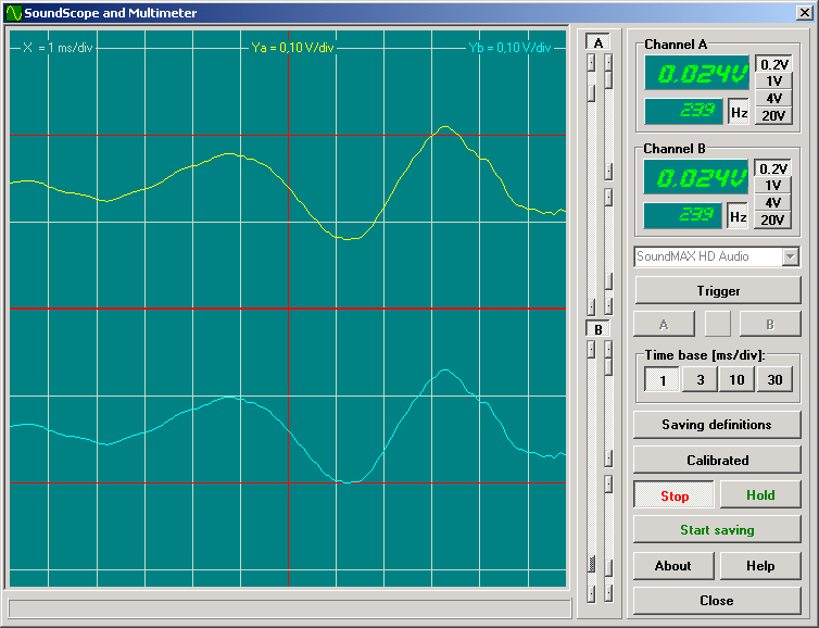
A basic working of the gesture recognition system can be understood from the following figure: 


Applications of Gesture Recognition Technology
While the initial need of gesture recognition technology was only to improve the human computer interaction, it found plenty of applications as usage of computer went widespread. Currently, the following applications of gesture recognition technology are there:
·    In Video Game Controllers:  With the arrival of 6th generation video game consoles such as Microsoft X-Box with Kinect sensor, Sony PS3 with motion sensor controller, gesture recognition was widely implemented. In X-Box, often the user is the controller and has to perform all the physical movements that they desire the character in the game to do. For instance, one has to imitate kicking a football if he is playing football on any of the above listed gaming console. The Kinect sensor has a camera that catches the motions and processes it so that the character exactly does it.
In Sony PS3, users have to move the controller in such a way so that it imitates the action the user wants the character in the game to perform.
And in XBox 360 I have already put an Article on my blog.

·   Aid to physically challenged: People who are visually impaired or have some other complexity in their motor functions can take help of gesture based input devices so that there is no discomfort while they access computers. Also, these days machine wheel chairs are coming with gesture based systems. All that is required from the user in here is to lightly move hands on the panel at the arm rest of the wheel chair. The movements of the hands will act as a controller and speed as well as direction can be easily controlled.
Shown below is a typical example of gesture controlled wheel chair.
Gesture Controlled Wheel Chair
·  Other Applications: Gesture recognition technology is gaining popularity in almost every area that utilizes smart machines. In aircraft traffic controls, this technology can aid in detailing every part of location information about the airplanes near to the airport. In cranes, this can be used instead of remotes so that easy picking and shedding of load can be load at difficult locations.
Smart TVs are nowadays coming with this technology making the user carefree about the remote and allowing him to use his hands for changing the channel or volume levels. Qualcomm has recently launched smart cameras and tablet computers that are based on this technology. The camera will recognize the proximity of the object before taking the picture and will adjust itself according to the requirements. The tablet computers with this technology will ease out the task where user has to give presentations or change songs on his juke box. He can browse all the data just by waving his hands around. Various touch screen smart phones are also incorporating this technology to provide easy access. Gesture recognition technology can also be used to make the robots understand the human gestures and make them work accordingly.
GESTURE RECOGNITION CHALLENGES
1.      Latency
One of the key challenges in gesture recognition is that the image processing can be significantly slow creating unacceptable latency for video games and other similar applications.
2.      Lack of Gesture Language
Since common gesture language is not there, different users make gestures differently. If users make gestures as they seem fit, gesture recognition systems would certainly have difficulty in identifying motions with the probabilistic methods currently in use.
3.      Robustness
Many gesture recognition systems do not read motions accurately or optimally due to factors like insufficient background light, high background noise etc.
4.      Performance
Image processing involved in gesture recognition is quite resource intensive and the applications may found difficult to run on resource constrained devices like PDA.
The rate of user acceptability of gesture recognition systems will be driven by how fast and wide spread gesture recognition becomes established and accepted in our everyday lives including other environments in which human interaction with machines takes place. These include interactions in the office, home, banking, gaming and other leisure activities. 

During the next few years, Gesture recognition is most likely to be used primarily in niche applications because making mainstream applications work with the gesture recognition technology will take considerable effort than it’s worth.